(800) 255-0088
Keep ’em On The Road®
| QTY | Part # | Description | Unit Price | Amount |
| Parts Total: | |
| Delivery & Handling: | |
| AIR: | |
| Core Charges: | |
Order Total:
| QTY | Part # | Description | Unit Price | Amount |
| Parts Total: | |
| Delivery & Handling: | |
| AIR: | |
| Core Charges: | |
Order Total:
 Tools Needed
Read ahead a paragraph or two at a time so you can plan ahead. Lay out items as you dismantle the car and match them up with the new parts. Lay out all carpet pieces and to match location and size.
Keep the parts for each area labeled with masking tape and marking pen for easier location later. Small containers such as plastic film canisters or baby food jars that can be taped to the larger parts come in handy. Don't throw all the parts into one container, as you may forget which piece went where.
Don't throw away anything until you are sure that you won’t need it again. This is a good idea anytime with an older car, considering the decreasing availability of parts.
Where holes are needed in new panels for screws or rivets, place the old panel on top of the new panels and tap the awl firmly with a hammer to punch the pilot hole at each spot. Use the old panels or a piece of cardboard under the area where you are working to keep from damaging your work area.
Use a knife or scissors to trim carpet and other material. You may lightly tap the material with a hammer to aid sticking the carpet down and removing wrinkles.
Clean and vacuum as you go so you eliminate having old abrasive dirt under your new interior. Keep your hands clean and dry while working with new carpet and vinyl.
When gluing, apply adhesive to both surfaces and allow to dry slightly before joining.
Use a good quality cleaner designed to remove glue from carpets and upholstery to remove overspray or glue spills.
Rivets will have to be drilled out with an electric drill and a 1/8" drill bit. If a rivet starts to spin as you drill, hold it in place with the tip of a flat screwdriver and then place the drill at a slight angle.
Disconnect the battery cables before working, to avoid the possibility of shorting out anything while working. This would be a good time to check the condition of the floor boards, doors and any other body sections for rust, corrosion and wear. Repair these before installing your new interior.
 Figure 1
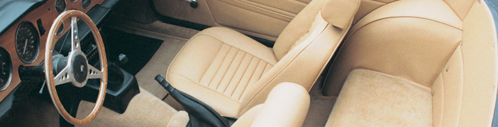
Remove convertible top or hardtop, refer to a workshop manual for either of these instructions. Remove both seats from the vehicle. The seats are attached to the seat frames by two 1/2" nuts and bolts at the front of each seat. Remove the seats from the car (Fig. 1) and then using a 7/16" socket remove the four bolts holding these frames to the floor.
 Figure 2
 Figure 3
 Figure 4
 Figure 5
 Figure 6
 Figure 7
 Figure 8
 Figure 9
The under seat carpets are held in place by the seat frames. The front footwell carpets are held by carpet clips which snap out from studs in the floor.
You now need to remove the center dash bracket (Fig. 2) that has legs on either side of the gearbox tunnel. Remove the two shaped tunnel knee pads (Fig. 2) that are situated in front of this bracket by taking out the Phillips screws at the far end, then push the panel forward and it will come free.
The dash bracket is held in place by four 7/16" bolts on the floor and two 1/2" nuts and bolts under the dash rail. If a radio is fitted, we suggest you remove this completely, as this will allow you to remove this bracket from the car. If necessary put tape on the wires and mark accordingly.
You can now remove the bracket which will give you access to the gear shift boot and rubbers underneath (Fig. 3). The handbrake carpet and two front tunnel pieces can now be removed.
Place the front bulkhead carpet in position and cut/ slit where the accelerator rod and speedo cable pass through it (Fig. 6).
When satisfied, apply adhesive to both the back of carpet and bulkhead then stick into place.
Fit the two pieces of underfelt to the tunnel (Fig. 7) and then insert the two carpets over the tunnel to give you an idea how they will sit when finally fitted.
Insert the rubber boots in tunnel before finally fitting these carpets (Fig. 8).
You now must replace the dash support bracket carefully (Fig. 9), cutting holes in the carpet where necessary to allow for the four floor bolts.
Finish off this operation by replacing the necessary bolts to secure the bracket and then replace the radio. The radio speaker panels or knee pads can now be fitted by slotting the front bracket into the dash support bracket and then fixing the front with screws and cupwashers.
 Figure 10
 Figure 11
 Figure 12
 Figure 13
 Figure 14
 Figure 15
 Figure 16
The rear quarter panels and rear cockpit panel are held in place with a variety of Phillips screws (Fig. 10).
Remove these panels as well as the piece of material that runs down the 'B' post (Fig. 11) so that the paint between the rear quarter panel and door trim is covered.
Next, the bracket at the base of this post needs to be covered with the shaped panel and corresponding material (Fig. 12). Note the positioning of the material of the board.
Bend the top of the board so that it will sit on the top of the bracket, while the extra material as can be seen (Fig. 13) is adhered to the outside of the metal bracket and returns up to cover the lip where the door trim fits.
You are now in a position to fit the sill carpets and front scuttle panels. The long vinyl flap will eventually be adhered over the sill lip (Fig. 13) and will be covered by the door trim. Apply adhesive to the rear of the carpet and to the metal sill, allow to go tacky, position and press firmly into place.
The scuttle panel can be fitted now. We suggest you lay the old panel over the new panel so you can transcribe holes for screw attachment (Fig. 14).
This will make the panel easier to fit and you can utilize the old holes in the bodywork (Fig. 15). The door trim can now be refitted to your car.
The last two pieces of carpet can now be removed. These are the two fitted over the rear axle area and are probably felt backed (Fig. 16).
 Figure 17
 Figure 18
 Figure 19
 Figure 20
 Figure 21
 Figure 22
 Figure 23
 Figure 24
In the packet with the wheel arch covers there are pieces of foam backed nylon, which are glued onto the metal arches to soften any undulations in the metal (Fig. 17).
Apply adhesive to the back of foams and the metal and by hand trimming create a nice round shape to wheel arches (Fig. 18).
The vinyl covers are only held to bodywork by applying glue to their outer edges.
Start at the top of the arch by laying the piping just inside of the vertical bracket (Fig. 19). Apply adhesive to both surfaces, allowing it to get tacky and stick down. Allow adhesive to dry thoroughly as you will need to pull the cover down to create tension and not create wrinkles.
The important part about this operation is to keep the inside flange of the piping turned one way or another to allow enough room for the seat belt bolts and to keep the piping going in as straight a line from top to bottom as possible. Apply glue to the outer edges of the bottom area of the vinyl, allow to dry, then pull on the piping, tensioning the material and stick to the floor area. Allow to dry, then pull and push the other edges to release any wrinkles. When you can see what the end result will look like, apply adhesive to the outer edges of the vinyl and corresponding bodywork and then glue into place. You will have to cut and trim in one or two areas, but this will become apparent when fitting.
The rear quarter panels and rear cockpit panel can now be fitted. Do the same as you did with the scuttle panels and lay the old panels over the new panels to transcribe the holes (Fig. 20).
Fit the special panel clips into the quarter panels, align and press into place, having previously accounted for the hole required for the seat belt bolt (Fig. 21). Make sure the top of panel is level with the bodywork, then fit the remaining screws and cupwashers and finally the cap that finishes off the door trim end.
The next stage is to fit the new carpet pieces over the rear axle box section.
Lay down the underfelt and trim where necessary (Fig. 22), then glue to the bodywork.
Apply the small oval piece over the axle bump making sure the larger piece that fits over it covers any raw edges (Fig. 23). Then glue the larger piece in centrally, making sure that it sits up against the brackets properly by the fuel tank area.
When fitted the cockpit panel is bent slightly along its length (Fig. 24). Screw this panel into place, making sure the end flaps of the rear quarters are tucked behind the cockpit panel.
 Figure 25
 Figure 26
The door handles are held in place by small spigots found between the flange of the handle and the door panel. These can be pushed out using a thin small screwdriver or a strong piece of wire.
The panels are held onto the door by panel clips. Push a flat ended screwdriver behind the panel to release the clips (Fig. 25). Note how the clips are fitted and positioned in your old panel then insert the new ones into your new panel.
Do not cut any holes for the handles at this stage. Proceed to clip the new panel onto the door, adjusting the clips where necessary. On early models with a chromed door handle, you will see the square spigot pushing into the vinyl material.
Cut across here with a sharp knife (Fig. 26) and the spigot will come through the material. Proceed by putting back the necessary hardware.
 Figure 27
 Figure 28
 Figure 29
 Figure 30
 Figure 31
The seat belts can now be refitted. The carpet with the handbrake boot can also be fitted at this time, making sure carpet sits down well (Fig. 27).
We suggest that you apply glue to the edges that will lie on the floor, so that when you use the handbrake, the carpet piece does not move around.
Lay out the underfelt pieces on the floor and trim where necessary (Fig. 28). The rear floor carpets are not fixed in, but held down by the seat frames, so all you have to do with these is cut small holes for the insertion of the seat bolts.
The front footwell carpets are held in place by special carpet clips supplied with the kit. If you have the old studs in the floor to hold these clips use them, if not there are some new ones in the kit.
With the carpet in the correct position, mark with a piece of chalk on the carpet the center of the stud below it.
Now push the pronged piece centrally through the carpet (Fig. 29), turn it over and place the flange onto the spikes (Fig. 30) that are sticking through, then turn these spikes over to secure both pieces together.
You will need at least four clips per footwell (Fig. 31).
The seat frame brackets can now be reinstalled.
 Figure 32
 Figure 33
 Figure 34
 Figure 35
 Figure 36
 Figure 37
 Figure 38
First separate the new left hand and right hand seat foams and seat covers. They are slightly different and should be marked left hand and right hand for positioning.
Keep one of the seats together to use as an example to check your work against until the first seat is completely recovered. Do not worry if the headrests do not come out at this stage.
Turn the seat upside down on the work bench and you will see that the seat tipping release mechanism is held in place by four Phillips screws (Fig. 32). Remove these screws, if possible, as they are generally rusted solid. If necessary drill the screw heads off to release the handle.
You will now see that the rear of the seat back cover is stuck to the frame.
Peel away and you will find some more flaps clipped to the frame by seat clips (Fig. 33). Remove these with your flat ended screwdriver and note how these flaps are situated. Now go to the bottom of the seat back side skirts which you will note are fairly solid.
At the bottom the cover has cardboard inserts with metal plates attached (Fig. 34), which in turn are clipped into brackets on the seat frame.
To release these, pull down and they will come free. Pull the cover free from the bottom of the seat and then from the front pull out the internal flap which is inserted through the foam cushion.
The cover can now be pulled up (Fig. 35) until you come to the headrest which should still be in place. Peel the cover up and over the headrest stalk and you will see a spring clip coming out of the stalk. Press this in with a screwdriver and the headrest will pull out. Remove the seat back foam from the frame.
Now you can remove the base cover assembly. Note how it is held onto the frame by seat clips which can now be removed (Fig. 36).
Peel the unclipped skirt up and over to see how the cover is attached to the foam cushion (Fig. 37). The frame foam wrap can also be removed as can the seat diaphragm (Fig. 38). Finish dismantling by inspecting the frame and carry out any repairs, etc., before cleaning and painting.
 Figure 39
 Figure 40
 Figure 41
We are assuming that along with the new seat covers, you will also be fitting new seat base diaphragms, base and seat back foam cushions. It may be necessary to also fit new seat back straps, but usually these are in reasonable condition and may only need repairing if they have lost tension.
When fitting the new base diaphragm (Fig. 39) we suggest you clamp frame to the workbench for safety reasons. Strong pliers are recommended.
A foam wrap, included in foam kit, is adhered to the base frame under the seat foam. Apply adhesive to both surfaces and stick as shown (Fig. 40).
The base seat cover has cotton calico flaps around the center fluted area. These need to be stuck under the raised edges of the foam (Fig. 41).
 Figure 42
 Figure 43
 Figure 44
 Figure 45
 Figure 46
 Figure 47
 Figure 48
 Figure 49
 Figure 50
 Figure 51
 Figure 52
 Figure 53
 Figure 54
 Figure 55
 Figure 56
 Figure 57
Slit the foam enough to allow these flaps to be tucked under and glued (Fig. 42) making sure the cover is central on the foam cushion (Fig. 43).
The foam with its loose cover can now be adhered to the frame (Fig. 44). Allow to dry. Roll the skirt over the foam. This will give you an idea how the finished base will look and where to cut to allow the skirt to go around the frame.
Peel back the skirt and glue both the calico flap and the top of the foam as shown (Fig. 45) and allow to dry.
Pull over the skirt again (Fig. 46) and tension and clip in place (Fig. 47).
The rear flap goes under the reclining mechanism main spring that runs along the rear of the frame (Fig. 48) and is clipped and glued into place (Fig. 49).
We suggest you cover the new base cover to avoid spilling any adhesive onto it. Glue the seat back foam (Fig. 50) to frame.
With the seat kit we have supplied four pieces of shaped cardboard inserts that fit into the vinyl pockets at the base of the side skirts.
Transfer the metal brackets from your old inserts (Fig. 51).
Fit the inserts into the pockets as shown (Fig. 52) and snip the vinyl back to expose the brackets (Fig. 53).
Either staple or glue the vinyl to the board.
Glue a piece of the plastic bag to the top surface of the seat back foam (Fig. 54), this will allow the new cover to slip easily over the foam.
Now slide the new cover over the foam (Fig. 55) and gradually work it down. Insert the inner calico flap through the slit in the seat back foam, behind the straps and down to the bottom of the frame. This flap will eventually pull the center of the cover into position to give the correct shape.
By pulling the sides of the cover down, the clips will eventually slot into the corresponding bracket in the frame and will hold the cover in the correct position.
Tension the inner calico flap by pulling it around the rear frame bracket (Fig. 56) and clip in place.
Now go to the front and insert the front flap through the frame. After tensioning and adjusting any wrinkles, clip over the bar where the calico flap is positioned (Fig. 57). The pipings should also be clipped in same method.
The back flap can now be clipped in place, but you will need to make some holes in the vinyl to allow the screws holding the tipping mechanism to be inserted. Screw this mechanism into place, replace reclining lever handle and then the seat runners. The seat can now be returned and bolted back into the car.
 Figure 58
 Figure 59
 Figure 60
Remove the two Phillips screws located on the underside of the headrest (Fig. 58). You will see that the cover is held by staples which can be taken out using your screwdriver. Now remove cover by turning it inside out and peel it away from the foam. You need to reverse this operation to fit the new cover.
Peel the new cover over the foam (Fig. 59) very carefully so as not to tear the cover, then mould it into position. If your old foam has shrunk a little, add a slither of foam to one or both ends.
Using either tacks or a staple gun, secure the cover as shown and then replace the plate on the bottom (Fig. 60). Lastly the headrest can be installed back on the seat back and away you go!
With all of your new interior kit installed, you’re ready to reassemble your car.
Replace the convertible top and the top retainer bar in the same manner as they were removed.
Reconnect your battery.
You did it yourself! Yes, it was work, but the finished job was worth it. Go ahead and smile… you earned it. This is what pride is all about!